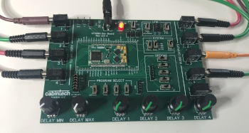
CT3680-DEV / FXCORE-PILOT Development Board

Assembly, Testing, and Usage of the CT3680 and FXCore Pilot developoment boards

CT3680 / FXCORE PILOT Bare Board Parts

For CT3680-DEV and FXCORE-PILOT Board Version 2.1

The following is the complete component list to populate a CT3680-DEV or FXCORE-PILOT development board. All these parts are included when the board is purchased as a kit. Some items are optional depending on how the development board is to be used and your particular application (see Optional Sections below).

Note that the switches have two footprints to support 2 different model/brands of switches, you can use either one, or any other SPDT with a matching footprint.

We do not endorse any particular supplier for these parts, we provide the list below only for your convenience.

DescManufacturerPart NumberQuantitySupplier Links
CT3680 Module Cabintech CT3680 1 Cabintech
2.5mm Mono TS Jack Switchcraft 35RAPC2AV 8 Digikey
2.5mm Stereo TRS Jack
For CT3680-DEV only
Switchcraft 35RAPC2BV4 1 Digikey
SPDT Mini Switch C&K
Chanzon
JS102011CQN
12D00G
10 Mouser
Amazon
Momentary Pushbutton Switch Jameco ValuePro DTS1212-R 2 Jameco
10K Linear Potentiometer TT Electronics PTV09A-4020S-B103 6 Digikey
2.1mm/5.5mm Power Barrel Connector Tensility International Corp 54-00133 1 Digikey
Red LED Sun LED XLUR12D 1 Digikey
300 Ohm 1/8W Resistor Lumimax Optoelectronic Technology MF1/8W300RFTB 1 Digikey
2.54mm (0.1in) Male Header Pins Envistia 65 Amazon
2.54mm (0.1in) Header Shunts Baeimstwr B09V1B3XMG 10 Amazon
Rubber Feet Bumper Specialties Inc. BS06BL05X10RP 4 Digikey
Knurled 6mm Shaft Knob CustomyLife HM5815-M 6 Amazon

Optional Parts

Some parts can be omitted depending on the intended development. Any of them can be added later if the need arises.

Kit Assembly Guide

Welcome! Follow these steps to to assemble the CT3680-DEV or FXCORE-PILOT development board.

Included Components Checklist

Component Quantity
Bare PC board 1
40-pin breakable header pin strips 2
10K ohm potentiometers 6
Potentiometer knobs 6
Mini switches (1 spare) 11
Mono 3.5mm jacks 8
Stereo 3.5mm jack (FXCORE-DEV only) 1
Power jack 1
330 ohm resistor 1
Red LED 1
Momentary pushbutton switch 2
Jumper blocks (shunts) 10
Rubber pad feet 4
CT3680 Module & Reference Card 1
Safety First: Work in a well-ventilated area, wear safety glasses while clipping leads, and follow safe soldering practices.

Assembly Steps

  1. Verify Kit Contents: Check the list above, then do the following steps to assemble the board. We recommend this sequence which builds from the shortest components to the tallest.
  2. Note the CT3680 Serial Number: Note the serial number that is written on the back of your CT3680 module. This may be needed for future support purposes but will be hidden once the module is mounted on the PCB. We recommend writing the SN somewhere (front or back) on the development board PCB with a permanent marker.
  3. Solder CT3680 Module:
    1. Position the module carefully on the board using the silkscreen outline as a guide. Be sure to note the correct orientation of the module using the pin-1 orientation indicator. Be sure the half-hole vias on the edge line up equally with the pads on both sides of the board (a good magnifying glass, microscope, or jewelers loupe are useful).
    2. Use a bit of tape or rubber bands to keep the module in position while the first one or two connections are soldered. Then the tape can be removed to solder the remaining connections.
    3. Use a fine-tip soldering iron to heat the pad, melt some solder into the half-hole and on the pad, then drag the tip away along the pad to make a good fillet of solder connecting the module to the board.
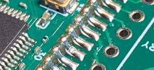
      A close up of the module solder joints.
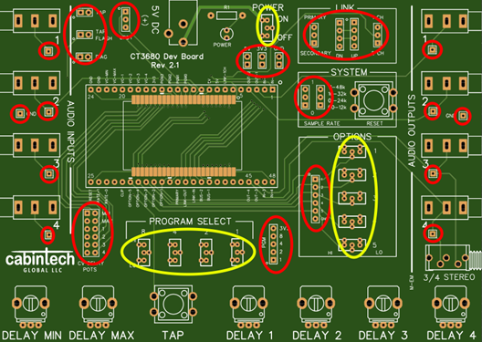
  4. Solder Header Pins: There are 65 total header pins. Locations are shown circled in red in the board diagram below. (Be careful not to solder header pins into switch locations shown in yellow.)
    Header Pin Soldering Tips
    • Use a rubber band to hold header strips in place while soldering from the back side.
    • Solder the single pins after all the multi-pin strips are done, turning the board over to hold the pin in place while soldering on the back side. When done soldering, check that all pins are straight and perpendicular to the board
    CT3680-DEV development board.
  5. Solder Mini Switches: Solder the (4) program select, (5) option (switch), and (1) power switch in the locations circled in yellow in the board diagram above. Orientation does not matter. Orientation is not important for these switches.
    Switch Soldering Tips
    • Like the header pins, a rubber band around the board can hold switches in place while soldering from the back side.
    • Solder 1 pin of each switch, then remove the rubber band. Reheat the pin and seat the switch into position, then solder the remaining switch leads.
    • After soldering, slide each switch back and forth a few times to clean the contacts.
  6. Solder LED and Resistor: Solder the resistor (R1) and red LED (POWER) in the power section. Be sure to note the orientation of the LED, it has a flat side to match the outline on the board.
  7. Solder Pushbuttons: Solder the TAP and SYSTEM RESET pushbuttons. They can be installed in either of the 2 possible orientations.
  8. Solder Mono Jacks: Solder the (4) AUDIO INPUT (4) AUDIO OUTPUT jacks.
    Jack Soldering Tips
    • Install 4 jacks in a row at a time. Insert the jacks and wrap the board with a rubber band to hold them in place. The band may not hold them exactly in place or tight to the board, that is OK. Lightly solder only 1 pin of each jack. Remove rubber band, then on each jack re-heat the soldered pin and press the jack properly into place and alignment. Now fully solder all pins of all the jacks.
    • Use a larger soldering iron tip for the large solder lugs of the jacks.
  9. Solder Stereo Output Jack (CT3680-DEV only): Solder the "3/4 STEREO" audio output jack (CT3680-DEV only, the FXCORE-PILOT does not have this jack). Use the same techniques as the mono jacks in the prior step.
  10. Solder Power Jack: Solder the 5V power jack.
  11. Solder Potentiometers: Install the (6) potentiometers (labeled on the CT3680-DEV board as "DELAY-XX", and "POT X" on the FXCORE-PILOT board). Insert the 3 signal legs, squeeze the side tabs and push down to clip the pot into the board. Check that the 3 signal pins are in the holes and slightly projecting from the back side of the board. Solder the 3 signal pins and 2 support tabs on each potentiometer. Use a larger soldering iron tip for the support tabs.
  12. Install Potentiometer Knobs: Press-on the potentiometer knobs. The kit may have 2 different colors of knobs (2 of color "A", 4 of color "B"). If so, use color "A" for the first 2 pots and color "B" for the last 4 pots.
    Knob Instll Tips
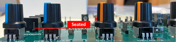
    • For proper registration (orientation) of the knob, rotate the pot fully counterclockwise, align the knob pointer with the lower-left corner of the pot body, then press the knob on the shaft. It can take some force to fully seat the knob (it may or may not "snap" in).
    • Check that all knobs are fully seated, the skirt of the knob should come down to the body of the pot: Alighnment of seated knowbs.
  13. Install Rubber Feet: Install the (4) rubber feet on the back of the board by peeling them from the sheet and pressing them on as close to the 4 corners as possible (avoid placing on top of any component pins).

Testing the Development Board

This test procedure will verify power, FXCore operation, and audio channels of a CT3680-DEV or FXCORE-PILOT development board.

  1. Set switches as follows:
    1. POWER: OFF
    2. OPTIONS ("SWITCHES" on Pilot board): HI
    3. PROGRAM SELECT: All HI (This selects program #15 which is used for testing)
  2. Set header jumpers (shorting blocks) as follows:
    1. LINK section : Connect center pin and upper (PRIMARY) pins on left header, connect center pin and 1 CH on right header.
    2. SYSTEM section: Connect center pin and upper (1) pins of both headers for 48kHz sampling rate.
    3. CV DELAY POTS (labeled "POTS" on Pilot board): Connect all sets of 2 pins (left-right pairs)
    4. No other header jumpers should be installed.
  3. Verify your power cable before connecting:
    1. 2.1mm center pin, 5.5mm outer ring.
    2. Use a multimeter to verify that the center pin of the power plug is +5V and the outer barrel is GND.
  4. Connect your power cable to the POWER jack and turn the POWER switch ON.
  5. Observe red LED POWER light is on, and a white LED on the module is flashing. This verifies the system is powered and running properly.
  6. Program 15 passes each of the 4 channels to their respective outputs with no modification (e.g. output 1 will have the signal on input 1, output 2 will have input 2, etc). You can test each channel by applying an audio signal to the input and observing the same signal on the corresponding output.

Power Supply

The power section of the dev board has a 2.1mm power jack (center positive) for +5V power input, an ON/OFF switch, and a LED. The ON/OFF switch allows control of power to the board without removing the power plug. Double header pins are supplied for off-board access to 5V, 3.3V, and GND. When using multiple development boards it is handy to jumper the 5V supply and GND lines together so only one board needs to have a power plug. Do not tie 3.3V supplies of multiple boards together. Each board generates its own independent 3.3V supply via a regulator on the CT3680 module.

Program Selection

The board has 4 program selection switches to allow selecting the program. The program select lines are also made available on header pins so program selection can be controlled off-board (for example, by a microcontroller). When driving the program select lines off-board, the switches must remain in the LOW (off) position.

Note that the program select lines are labeled "1-2-4-8" on the CT3680-DEV board to correspond to the program numbering (1-16) used in the CT3680 Reference Guide. The lines are labeled "0-1-2-3" on the FXCORE-PILOT to correspond to the FXCore datasheet specification.

Option/Switch Selection

The board has 5 selection switches in the OPTIONS section (SWITCHES section on the Pilot) that allow control of various program-dependent settings. Header pins make these controls available to an off-board controller. When driving the pins off-board, the switches must remain in the HI position.

System Settings

The SYSTEM section has 2 jumpers that select one of 4 sampling rates. The legend on the board shows the proper position of the jumpers for 48kHz, 32kHz, 24kHz, or 12kHz sampling rates. Note that sampling rate changes do not take effect until the system is reset or power cycled. There is a push button switch in the SYSTEM section to reset the system.

Potentiometers

The 6 potentiometers along the bottom edge of the board are connected to the CT3680/FXCore module and can be used to control various program-dependent parameters. Each pot produces a control voltage in the range 0V to 3.3V. At the full counterclockwise position, the CV voltage will be 0.0V, full clockwise is 3.3V. The potentiometers are linear. If CV is to be supplied off-board, the CV control jumpers should be removed, and the external CV signals should be supplied to the rightmost pins of the jumper block (closest to the program switches).

Note potentiometers are labeled as "DELAY-XX" on the CT3680-DEV board to correspond to the CT3680 Reference Guide. On the FXCORE-PILOT board they are labeled "POT X" to correspond to the FXCore datasheet specification.

Audio Input/Output

n 3.5mm TS mono jacks are provided for the (4) audio input and (4) audio outputs of the system. Each input and output also has a single header pin that is handy for clipping test leads. On the CT3680-DEV board (only) there is also a single TRS stereo output jack that combines audio outputs 3/4 into a left/right stereo pair (used by some of the stereo programs of the CT3680).

Tap Tempo

n The board has a momentary push button style switch along the front edge between the CV controls. When depressed this button shorts the TT_IN pin to ground. This button can be used to simulate a typical tap tempo foot switch. To use your own external switch, connect it to the 2-pin header labeled TAP in the upper left corner of the board. The tap tempo LED signal is also available on a 2-pin header in the same area, labeled TAP FLASH. Pin1 of the headers is the signal pin (marked with a small circle), pin 2 is GND.

Multi-Module Linking

The linking (or "chaining"") feature allows multiple development boards to be connected together and pass either 1 or 2 channels of digital audio from one board to the next. This allows multiple boards to be used together to create a larger system with more audio channels and longer delay times. Note that this feature is not supported natively by the FXCore but is implemented in the CT3680 module used by the development board.

The board has two headers in the LINK section for linking modules as described in Chaining Multiple Modules on page 49. Each header has 4 pins. The primary module development board should have its “DN” (downstream) header connected to the secondary module board’s “UP” (upstream) header. Connect all 4 pins of the header from one board to the next. If a secondary board is to be connected to another secondary board, connect its DN header to the next board’s UP header, and so on, down the chain of boards.

There is a jumper in the LINK section to set the module as primary or secondary. There can be only 1 primary module in a chain of modules (see Chaining Multiple Modules in the CT3680 Development Guide). Changes to the primary/secondary jumper only take effect when the system is reset or power cycled. To reset the system use the pushbutton switch in the SYSTEM section.

For secondary module boards, the jumper in the LINK section can be set to “1 CH” for single channel linking, or “2 CH” for dual channel linking.

Linked development boards.
(Note this photo shows older V1 development boards).

Schematic

Dev board schematic.

News: Facebook page.
Reviews: Trustpilot
Home
Semiconductors
Articles
About Us
Contact Us
V 13.36